555 Timer Schematic : Speed Controller Using 555 : 555 signals and pinout (8 pin dip) figure 1 shows the input and output signals of the 555 timer as they are arranged around a standard 8 pin dual inline package (dip).
555 Timer Schematic : Speed Controller Using 555 : 555 signals and pinout (8 pin dip) figure 1 shows the input and output signals of the 555 timer as they are arranged around a standard 8 pin dual inline package (dip).. Why to use timer 555? There are simple circuits for beginners and advanced engineers. 555 signals and pinout (8 pin dip) figure 1 shows the input and output signals of the 555 timer as they are arranged around a standard 8 pin dual inline package (dip). More images for 555 timer schematic » The output voltage from the chip is around 1.5 v lower than vcc when high and around 0 v when low.
The internal block diagram and schematic of the 555 timer are highlighted with the same color across all three drawings to clarify how the chip is implemented:2. It was commercialized in 1972 by signetics. The 555 timer is a simple integrated circuit that can be used to make many different electronic circuits. In 2017, it was said over a billion 555 timers are pr. The 555 timer ic is an integrated circuit (chip) used in a variety of timer, delay, pulse generation, and oscillator applications.
Getting more amperage from a 555 output - Electrical ... from i.stack.imgur.com A popular version is the ne555 and this is suitable in most cases where a '555 timer' is specified. Jul 10, 2021 · the 555 timer is a simple integrated circuit that can be used to make many different electronic circuits. Derivatives provide two (556) or four (558) timing circuits in one package. The output voltage from the chip is around 1.5 v lower than vcc when high and around 0 v when low. These are easy to build 555 circuits for beginners and advanced engineers. The 555 timer is a simple integrated circuit that can be used to make many different electronic circuits. What are different modes of 555 timer? 555 & 7555, single/dual/quad, ultra low power, @ mouser & digikey
It is a affordable, stable and user friendly ic in application such as monostable and bi stable.
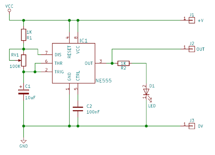
And now a full schematic of the 555 timer oscillator with single step and free run option. Jul 27, 2021 · 555 timer astable multivibrator circuit diagram from circuitdigest.com with this information you will learn how how the 555 works and will have the experience to build some. 555 supply (pins 1 and 8). It was commercialized in 1972 by signetics. In 2017, it was said over a billion 555 timers are pr. Jun 11, 2017 · 555 timer circuits (133) browse through a total of 133 555 timer circuits and projects including the timer's datasheet. Jul 24, 2021 · the circuit latches in either the q state or its refer block diagram of 555 timer ic given above: Jul 27, 2021 · the general 555 timer circuit schematic at the heart of the circuit is a lm555 ic, which includes 23 transistors, 2 diodes and 16 resistors on a silicon. Derivatives provide two (556) or four (558) timing circuits in one package. •1 timing from microseconds to hours • astable or the xx555 timer is a popular and easy to use for general purpose timing applications from 10 µs to hours or. The 555 timer is a simple integrated circuit that can be used to make many different electronic circuits. What is the maximum voltage that can be given to a 555 timer? 555 & 7555, single/dual/quad, ultra low power, @ mouser & digikey
And now a full schematic of the 555 timer oscillator with single step and free run option. Jul 24, 2021 · the circuit latches in either the q state or its refer block diagram of 555 timer ic given above: More images for 555 timer schematic » This pin connects to the negative side of the battery. In 2017, it was said over a billion 555 timers are pr.
How to Use a 555 Timer in Maker Projects | Custom | Maker Pro from maker.pro These are easy to build 555 circuits for beginners and advanced engineers. It is a affordable, stable and user friendly ic in application such as monostable and bi stable. This pin connects to the negative side of the battery. In this tutorial we will learn how the 555 timer works, one of the most popular and. What is the maximum voltage that can be given to a 555 timer? 555 & 7555, single/dual/quad, ultra low power, @ mouser & digikey What is a 555 timer and how does it work? A popular version is the ne555 and this is suitable in most cases where a '555 timer' is specified.
These are easy to build 555 circuits for beginners and advanced engineers.
The internal block diagram and schematic of the 555 timer are highlighted with the same color across all three drawings to clarify how the chip is implemented:2. It is a affordable, stable and user friendly ic in application such as monostable and bi stable. The output voltage from the chip is around 1.5 v lower than vcc when high and around 0 v when low. Derivatives provide two (556) or four (558) timing circuits in one package. In 2017, it was said over a billion 555 timers are pr. The 555 timer ic is an integrated circuit (chip) used in a variety of timer, delay, pulse generation, and oscillator applications. •1 timing from microseconds to hours • astable or the xx555 timer is a popular and easy to use for general purpose timing applications from 10 µs to hours or. And now a full schematic of the 555 timer oscillator with single step and free run option. These are easy to build 555 circuits for beginners and advanced engineers. What is the maximum voltage that can be given to a 555 timer? The 555 timer has two basic operational modes: This pin connects to the negative side of the battery. 555 timer tutorial bundle includes:
More images for 555 timer schematic » And now a full schematic of the 555 timer oscillator with single step and free run option. Why to use timer 555? This pin connects to the negative side of the battery. Jul 28, 2021 · the general 555 timer circuit schematic at the heart of the circuit is a lm555 ic, which includes 23 transistors, 2 diodes and 16 resistors on a silicon.
Analysis of 555-Based PWM Circuit | Math Encounters Blog from i0.wp.com This pin connects to the negative side of the battery. In this tutorial we will learn how the 555 timer works, one of the most popular and. There are simple circuits for beginners and advanced engineers. 555 supply (pins 1 and 8). A popular version is the ne555 and this is suitable in most cases where a '555 timer' is specified. 555 signals and pinout (8 pin dip) figure 1 shows the input and output signals of the 555 timer as they are arranged around a standard 8 pin dual inline package (dip). The 555 timer is a simple integrated circuit that can be used to make many different electronic circuits. Jul 27, 2021 · the general 555 timer circuit schematic at the heart of the circuit is a lm555 ic, which includes 23 transistors, 2 diodes and 16 resistors on a silicon.
Jun 11, 2017 · 555 timer circuits (133) browse through a total of 133 555 timer circuits and projects including the timer's datasheet.
The internal block diagram and schematic of the 555 timer are highlighted with the same color across all three drawings to clarify how the chip is implemented:2. In this tutorial we will learn how the 555 timer works, one of the most popular and. •1 timing from microseconds to hours • astable or the xx555 timer is a popular and easy to use for general purpose timing applications from 10 µs to hours or. 555 timer tutorial bundle includes: A popular version is the ne555 and this is suitable in most cases where a '555 timer' is specified. There are simple circuits for beginners and advanced engineers. The output voltage from the chip is around 1.5 v lower than vcc when high and around 0 v when low. 555 datasheet 555 duty cycle 555 metronome 555 reset function 555 time delay relay inverted 555 timer pulse generator. Jul 27, 2021 · the general 555 timer circuit schematic at the heart of the circuit is a lm555 ic, which includes 23 transistors, 2 diodes and 16 resistors on a silicon. What is the maximum voltage that can be given to a 555 timer? 555 supply (pins 1 and 8). The 555 timer is a simple integrated circuit that can be used to make many different electronic circuits. Derivatives provide two (556) or four (558) timing circuits in one package.


0 Komentar